Vertical Landing Rocket (Thrust Readings of a Rocket)

In order to ensure a descending rocket will land softly, a sensor system must be integrated to detect changes in height, velocity, rotations-per-minute (RPM) and thrust. The respective data is essential for proper communication between the microcontroller and the servo motor. The intended goal is to have our sensors output a single height value and to adjust the throttle of the propeller with respect to the velocity as the rocket descends.
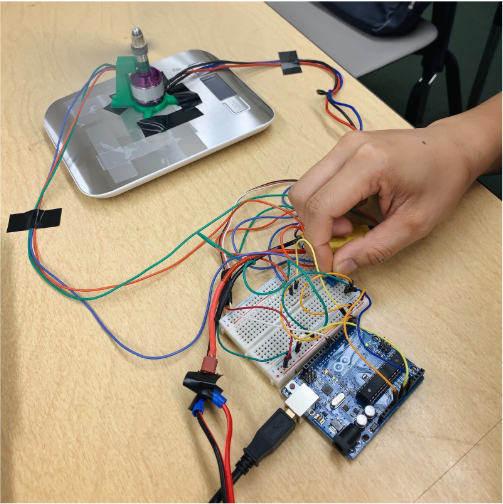
For this project, I designed and made an RPM sensor by using a Hall effect sensor and a magnet with the other team members. The Hall effect sensor uses the Hall effect theory and acts like a switch. We 3D printed a mold, which could hold a magnet against the shaft and also 3D printed a base, which would hold the Hall effect sensor in a permanent position near the shaft. When the motor spins, the magnet passes in front of the Hall effect sensor, changes the magnetic field for that duration that the magnet is in front of the sensor, and sends a signal to the Arduino, thus detecting the rotation.

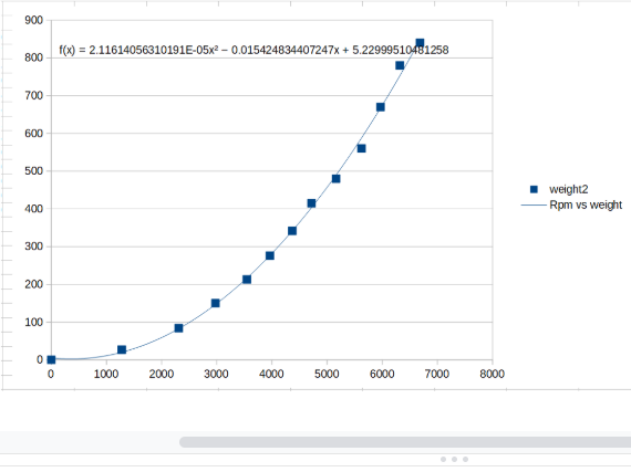
We used the RPM sensor we made and a scale to measue the RPM and the thrust. I also made a graph for RPM VS Thrust with the data, and the Graph above shows the relation between the RPM and the thrust (measured in Weight). We also used the data to make an equation. With the relation between the RPM and the thrust, we could now know how to control the rocket when it is landing.
By doing this project, I know how to design an embed system with Arduino and how to write code with Arduino.
Source: source code for the RPM sensor